Remote monitoring with Arduino (part 2)
February 2013 (550 Words, 4 Minutes)
In part 1 I have looked at the options available for the task of remote climate monitoring and settled on Arduino-based solution. In this we will discuss the design of the system.
General architecture
The high-level architecture is typical for Arduino: there is an Arduino-based board that collects the sensor data and passes it over USB to the PC that processes this data and uploads it to the database. A more parsimonious solution would be to build an Arduino board with an Ethernet or Wi-Fi shield and to connect it directly to the network, but I already had a tiny Atom-based PC (NetBox nT-535) running 24×7 and doing other tasks. Plus, Arduino library is fairly limited, so doing any more or less sophisticated data manipulation right on Arduino is difficult.
Since I needed to monitor 3 different locations (outside, crawlspace, and indoors), I could either run wires or work out some kind of wireless solution to communicate the data from different places. Wired solution is easy electronically but requires drilling holes and running wires around the place which is not fun. A good solution would not need that, so wireless was indeed the answer. In this case, I could do away with running 2 Arduinos: one sitting in the crawlspace and collecting the crawlspace temperature, outdoor temperature, checking the water level on the ground, and sending all this data to the “master” Arduino board that collected the indoor temperature and sent all collected data to the PC via USB.
Wireless communication
Fortunately, Arduino has a number of options when it comes to wireless communications: from WiFi to Bluetooth, to ZigBee. However most of these options are a big overkill. What is really needed is something similar to what those cheap indoor/outdoor thermometers are using, which is low-power RF communication. Fortunately, Arduino has plenty of options in this department as well. An inexpensive pair of a 315MHz receiver and transmitter can provide uni-directional communication between the “slave” and “master” units. The one that I settled on was a pair of modules from Sparkfun. They are small, cheap, and relatively easy to use.
Sensors
Since one of the objectives was to have fun and try different things out, I didn’t want to use the same model of the temperature sensor in three different places, instead opting for the following ones:
- Environmentally protected DS18B20 digital temperature sensor for crawlspace temperature monitoring.
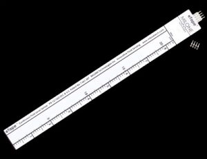
- Analog 10K thermistor for outdoor monitoring (one of the reasons to use this model is that it runs only 2 wires so it is easier to extend its reach)
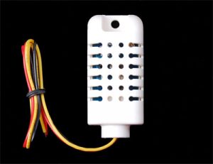
- Digital DHT22 temperature/humidity sensor for indoor monitoring (as a bonus I get the indoor humidity to observe).
Flood detection however is a completely different story. Flood sensors on the market are few and apart and they are not geared toward Arduino. Whereas the simplest flood sensor can be built very easily by running two wires that get shorted when covered by water, this is too volatile and crude (let alone the fact that it requires some salt in order to ensure conductivity). There are also some fairly complex mechanical options based on measuring the level of flotation of the moving part.
The one I finally settled on was an eTape liquid level sensor. In short, it is a variable resistor that reacts to the water pressure, which is exactly what I was looking for. On the downside, it is extremely sensitive to its placement, shape and inner tensions and it is also not cheap (about $40).
Final architecture
In its final iteration, the system consists of two Arduino boards. A “slave” board sits in the crawlspace. It uses AC power via a 5V AC adapter and it runs 3 sensors:
- Inside (crawlspace) temperature (DS18B20)
- Outside temperature (Thermistor)
- Water level (eTape)
The slave board periodically queries all sensors and sends all data via RF wireless to the “master” board, sitting inside the house. The master board has only one temperature/humidity sensor (DHT22). It combines all data and sends it via serial communication (over the USB) to the PC that performs further processing.
In the next part we will look into the actual implementation and issues I had to solve while building it.